Laser Cutting:
Now that the laser has been recovered from Dr Evil's "Shark with a Fricken' Laser" © and has been returned to the machine from which it was stolen, we can put it to good use.
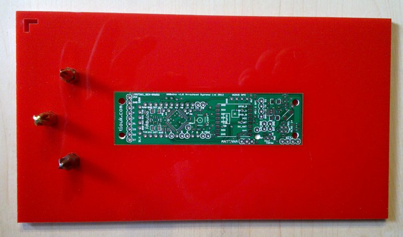
You have our PCB, but how do you solder all those parts on to it?
The smallest discrete parts on the HABuino board are size 0402 resisters and capacitors, these measure 1.0 × 0.5 mm (0.039 × 0.02 in), the processor that's going to do all the work, an ATMEGA328P-AU is a 32 pin TQFP and relatively large at 9mm (0.3 in) square with 32 pins, 8 on a side. However the TPS61200 boost converter is a 10 pin QFN package, 3mm (0.11 in) square with 5 pins on two opposite sides (who thought using those was a good idea?).
|
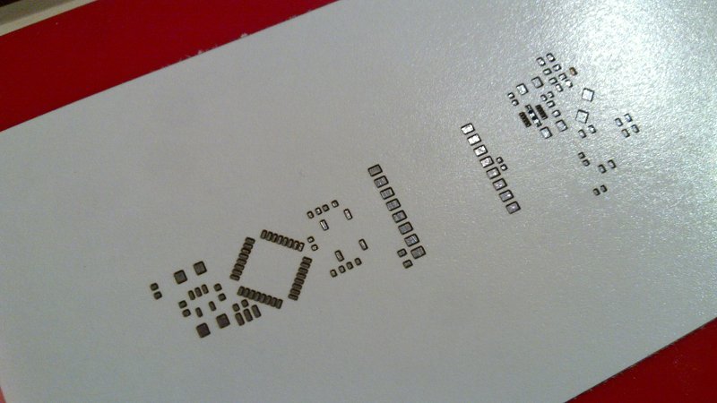
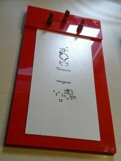
You might have read on the SMT page that solder is applied by a printing process, so you need to keep everything steady and aligned. Some people use tape and strips of PCB to hold things down, we have a laser cutter, so will use that to make a jig to hold everything, here's how. Like most laser cutters/plotters, ours supports several standard printing protocols. We will use a Vector drawing and print it to the laser. Vector graphics is a term to describe a drawing made up with geometric primitives, points, lines, polygons, arcs and circles. The laser follows these lines, the high frequency infra red light focused down on to the material, which vaporises separating the material on each side of the beam. You need a vector drawing package, we use an old version of Corel Draw as we got it with the laser, but you could use Inkscape, maybe Xaralx, probably FreeCAD and QCAD. We printed our PCB outline to a postscript file and imported it in to Corel Draw and on to layer 1. Next we made sure there was only one line, as sometimes you get two lines, one for each side of a line in the postscript file. Delete the inner, join the lines to make a shape and set the line thickness to the smallest possible. This line thickness is used for all subsequent pieces. |
 |
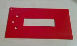 |
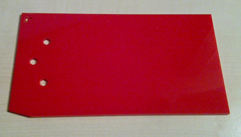
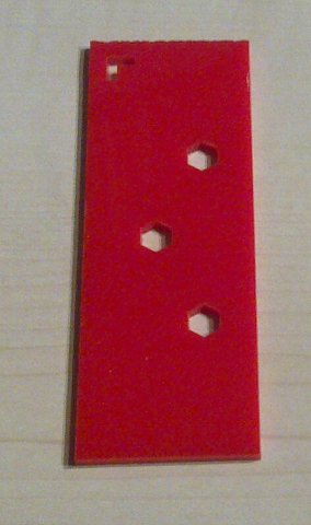
Add a new layer, number 2, draw a box around the outline, about 40mm wider all around, this is the PCB holder. Now add third layer for registration holes, we're going to add three, in a triangle towards the end of the holder. You could place circles here, but you would have to find and cut some correct diameter rod to assemble the jig. Instead use the polygon tool, set the number of sides to 6 and draw a hexagon, 6.35 mm across the flat which is 7.33 mm diameter. Put one in the centre of the short side 10 mm (0.4 in) from the end and a further two another 10 mm in but spaced 10 mm wider than your PCB. |
|
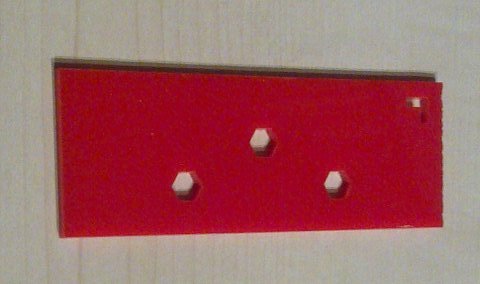
Why a hexagon? I'm sure you have one of those screwdriver sets which have changeable hexagonal bits, those bits are 6.35 mm or 0.25 in, so you can use three of those to align your jig. Add layer 4. Draw a box over the end of the holder, 10 mm longer than the hex holes, mine is 35 mm long and as wide as the first box or holder. We are nearly done, the last shape is a visual clue for you when using the jig, it can be any shape, positioned near an outer corner of the last box you drew, put it on a new layer, number 5. Save your work, in fact, save your work as you go. If you're prepared to loose 30 mins work save every 30 mins, if you only want to loose 5 mins work in case of a crash or other incident, save every 5 mins. Now we will cut 3 pieces, the layers to print are in brackets. 1. The outer box (2), three holes (3) and visual clue (5): Viola, you now have a Solder Cream Jig. If you notice, the corner is missing from our PCB support as we used a scrap piece of perspex for that bit. We also used some thin plastic to cut a couple of PCB outline sized packing pieces to bring the actual PCB to the level of the perspex PCB Holder for printing. |
 |
Laser